Description
1. Overview of Double-Acting Pneumatic Actuator
Double-acting pneumatic actuators operate by using air pressure to control valve opening and closing. When air is supplied to one side, the valve opens; when air is supplied to the opposite side, the valve closes. Unlike single-acting actuators, double-acting models rely on air pressure rather than springs for resetting, making them suitable for applications where maintaining position during air loss is critical.
2. Working Principle
When air enters the middle chamber between the pistons through air port (2), the pistons move outward, discharging air from both ends via air port (4). This action rotates the output shaft counterclockwise. Conversely, when air enters both ends of the cylinder through air port (4), the pistons move inward, discharging air from the middle chamber through air port (2), rotating the output shaft clockwise.
3. Technical Parameters
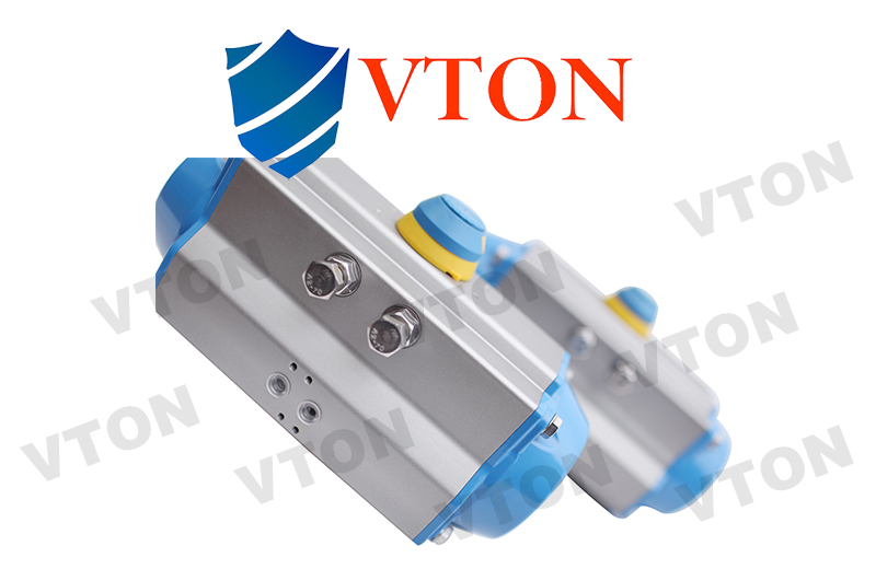
- Model: V-AT
- Body Material: Aluminum Alloy
- Air Supply Pressure: 2.5 ~ 8 Bar
- Switching Time: 0.5 ~ 8 seconds
- Torque Range: 3 ~ 13,000 Nm
- Compatible Valves: Butterfly valves, ball valves
- Accessories: Positioners, limit switches, air treatment units
4. Product Features
- Precision Control: Utilizes air pressure for accurate and stable valve operation.
- Durable Construction: Aluminum alloy housing provides strength and resistance to corrosion.
- High Torque Output: Designed for handling large valves and high-pressure systems.
- Versatile Compatibility: Supports butterfly valves, ball valves, and a variety of industrial accessories.
- Stable in Air Loss Conditions: Maintains valve position when the air supply is lost, ensuring safety and reliability.
5. Selection Guidelines
When selecting a double-acting actuator:
- Determine the required torque for the valve and apply a safety margin:
- Water vapor or non-lubricated liquid: +25%
- Non-lubricated slurry: +30%
- Non-lubricated dry gas: +40%
- Non-lubricated particle powder: +60%
- Clean, low-friction lubricated media: +20%
- Match the adjusted torque to the actuator’s output torque at the desired air supply pressure.
Example Selection:
For a ball valve requiring 200Nm torque with a 0.5MPa air supply and non-lubricated water vapor:
- Add 25% safety margin (200Nm × 1.25 = 250Nm).
- Use the output torque table to find a torque of 268Nm at 0.5MPa.
- Select model V-AT125.
6. Additional Information
- Action Time Testing Conditions:
- Ambient temperature
- 90° stroke
- Solenoid valve with 4mm diameter and Qn flow of 400L/min
- Air tube with 8mm inner diameter
- Clean, dry air at 0.6MPa
- No external load